TouchCAD 3D - A Combined 3D Modelling and Unfolding Program
by Laurie McGowan
(Appeared in WoodenBoat Magazine Issue #211, November/December 2009)
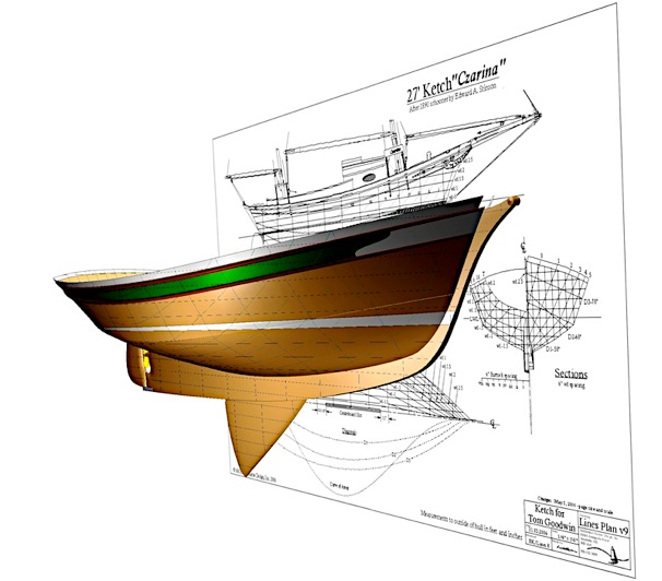
(Boat rendering copied directly from monitor,
from TouchCAD program - including lines plan background)
In the mid-1990s, I had a boat design epiphany: I was learning how to use a MacSurf (now MaxSurf*) while calculating most of the hydrostatics on a practice boat. What normally would have taken the better part of a week to do by hand appeared on the monitor in the time it took to click the button “Calculate Hydrostatics.” I remember my jaw dropping and an involuntary “oooh” escaping as a tidy list of numbers showing underwater dimensions and volumes, displacement, center of buoyancy, center of waterplane, and a bunch of other things I didn’t yet understand filled a small table. It was lovely. This powerful tool allowed more time for fun stuff: 3D modelling, drawing, and presenting clearly to clients and builders what was developing on the page. Less time would be needed for the tedious, error-prone stuff—the number crunching.
New boat design programs are appearing on the market every year, and some— fine for modelling very simple hulls—are available as freeware online. Usually, (definitely not always) the amount one pays is reflected in a program’s ability to best help complete whatever job is required. A few years back I discovered TouchCAD, a reasonably priced cross-platform (Mac and Windows) boat-design program that can do most of what other design programs can, and a few things that no other can touch.
TouchCAD was created by a Swedish structural engineer, Claes Lundstrom, who built boats in plywood as a teenager and later wanted a design program that could flatten sheet materials from compound-curved shapes. He couldn’t find anything that could do this, so he taught himself computer programming and developed an application that did everything directly on the surface being modelled, which I'll explain next.
Unlike most modelling software that sets up a grid of points to control splines (think flexible battens on the loft floor or design table) near the surface of what’s being modelled, TouchCAD uses control points that are part of the surface, to move it in 3D; these points can be added anywhere they're desired along the surface. As well as simplifying modelling, this feature allows TouchCAD to accomplish perhaps its most amazing feat: to dynamically update, and then unfold, compound shapes into accurate, flat patterns. Think of the surface of an orange – bent in three directions, then unpeeling it in one piece and laying it flat. The parameters of unfolds may easily be defined: panel orientation (horizontal or vertical); extra material for overlaps; where the unfolded parts join; number of pieces in the unfold; number of cuts, or darts, in panels; etc. This pattern may then be used with any sheet material (plywood, metals, plastics, fabric, or wooden plank stock). While a surface is modified, TouchCAD updates the unfolded version in real time. Conversely, the surface may be tweaked while in the unfolded view, then back in the modelling space it changes correspondingly. That’s the dynamic update part.
Lapstrake hulls and the strakes themselves may easily be developed in TouchCAD, as I did on a recent design, the NorseBoat 12.5. The boat was completely modelled in TouchCAD, and the program configured the lap locations on the hull very well. One problem arose, however. The builder found an inaccuracy in the unfolded strake patterns: after three strakes were installed, the patterns no longer fit, as too much edge-set was needed to install them. As Lundstrom and I discovered, I had only modelled the shared inside edge of the plank joints of a stitch-and-glue-type shape, though the boat was lapstrake. In a lapstrake hull, if you look at it right-side up, the bottom inside edge of the upper strake is lower than and outboard of the lower strake’s upper inner edge, and this slight inaccuracy had compounded by the third strake. There is a space between these two points that I wasn't taking into account. Now these factors are worked into the modelling process and I can change a round hull into, say, an eight-strakes-per-side lapstrake one, develop the unfolded strakes, and lay them out for full-sized printing (at a print shop) for accurate low-cost shop patterns in less than 30 minutes. Patterns for a multi-chined hull (that is, take a round hull and develop evenly spaced and accurate panels that don’t have to overlap, as in stitch-and-glue construction) can usually be generated in less than five minutes - once one has some familiarity with the program. Lundstrom shows how to do this in an instructional movie on the TouchCAD website. Strakes or patterns may be nested, or puzzled together, on a panel of building material within the program as well, reducing the amount of time needed to work out the most efficient use of materials.
Similar to most other marine modelling software any surface may easily be defined, changing how it looks and behaves (how or if it bends in a smooth curve, for example). Alterations to a surface may occur in the modelling space, in the Unfold window, and from within two Surface-Definition windows (where weights of materials, center of gravity, dimensions, etc. are listed). A very good 3D view of the model may be seen in the Render window, and it is here that movies (displaying the model in rotation, for example) may easily be made. I find this to be an excellent tool for showing progress or problems to clients and builders. Lundstrom has made many very helpful instructional movies, and they’re all available on the website for free. It’s like having someone show you how to cut a plank gain or keel rabbet for the first time: something much easier to watch and understand than it is to read about.
An existing set of lines may be used as a starting point for a new design. A picture of the plan, profile, and section views may be imported, scaled, and placed correctly in the modelling space. Then, because the control points are directly on the surface, these may be pushed and pulled so that the various surface contours line up with the background image. Photographs accompanied by a few measurements may also be used to model surfaces. I find this helpful when a client wishes for an adaptation of an existing design.
TouchCAD can accomplish simple hydrostatics calculations—displacement, center of buoyancy, LWL, draft, etc... In the Surface Properties window all the surfaces are defined, and weights or areas summarized, simplifying center of gravity, material lists, and sail area calculations. One may import and export a host of file types in and out of TouchCAD, and designs may be exported to rendering programs such as Artlantis, 3ds Max, Flamingo, or Cinema4D.
Why not design in these other programs to begin with? Why use TouchCAD? Perhaps because the alternative programs are too expensive, or they don’t work on boats, or because TouchCAD is accurate, fast, and fun to use. Yes, indeed, TouchCAD is fun. Lundstrom has obviously spent a lot of time working on the user interface, making the program easy to learn and use. It’s now the first program I go to when designing, and it’s the only one I’ve found that has the dynamically updated unfolding feature, which many wooden boat builders and designers would find useful.
* MaxSurf is a boat design program from Formation Design Systems, of Fremantle, Australia.
Laurie McGowan is a boat designer near the historic town of Annapolis Royal, Nova Scotia.
For more information, contact Lundström Design, Ekhagsvägen 7, 104 05 Stockholm, Sweden +46-8-15-46-63; fax +46-15 82 85; info@touchcad.com www.touchcad.com
---------------------
Here is a small copy of the movie, Final Presentation.mp4 , about TouchCad that I presented to the 2012 IBEX show in Louisville, KY.
Copyright 2001-2021 inclusive McGowan Marine Design, Inc.